
High-performance plastics are increasingly being used to replace materials like bronze, stainless steel, aluminium, and ceramics. The most popular reasons for switching to plastic include:
- Longer part life
- Elimination of lubrication
- Reduced wear on mating parts
- Faster operation of equipment/line speeds
- Less power needed to run equipment
- Corrosion resistance and inertness
- Weight reduction
With the many plastic materials available today, selecting the right one for your application may be intimidating. To help, we’ve created the following guidelines to assist those new to the world of engineering plastics.
1. What is the general application purpose?
2. What are the thermal requirements of the plastic material?
3. Which chemicals will the plastic material be exposed to?
-
The requirements for chemical resistance in any given application can be difficult to predict since concentration, temperature, time, and stress each have a role in defining suitability for use. For this reason, we strongly recommend that you test materials under end-use conditions.
Generally speaking, thermoplastics have the advantage of exhibiting a broad range of chemical resistance behavior, making it possible to select a plastic material that can perform to the specifications of your application.
For instance, nylons, acetals, and Ertalyte™ PET-P have chemical resistance properties that make them generally suitable for interaction with the chemicals in most standard industrial environments. Beyond standard applications, high-performance, crystalline materials such as Fluorosint™ filled PTFE, Techtron™ PPS and Ketron™ PEEK are more suitable for aggressive chemical environments.
4. Consider additional criteria
5. Which plastic shape is best for your part?
-
1. What is the general application purpose?
-
2. What are the thermal requirements of the plastic material?
-
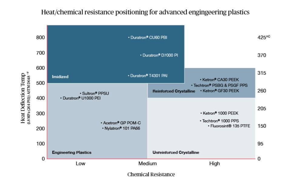
3. Which chemicals will the plastic material be exposed to?
-
The requirements for chemical resistance in any given application can be difficult to predict since concentration, temperature, time, and stress each have a role in defining suitability for use. For this reason, we strongly recommend that you test materials under end-use conditions.
Generally speaking, thermoplastics have the advantage of exhibiting a broad range of chemical resistance behavior, making it possible to select a plastic material that can perform to the specifications of your application.
For instance, nylons, acetals, and Ertalyte™ PET-P have chemical resistance properties that make them generally suitable for interaction with the chemicals in most standard industrial environments. Beyond standard applications, high-performance, crystalline materials such as Fluorosint™ filled PTFE, Techtron™ PPS and Ketron™ PEEK are more suitable for aggressive chemical environments.
-
-
4. Consider additional criteria
-
5. Which plastic shape is best for your part?
Looking to talk to a material selection expert? Get in touch with our specialist teams by filling in the contact form. We’re ready to meet your next challenge.
Contact us