Guide to machining plastic parts
What are the different methods of machining plastic, and what specifications must be considered to machine high-performing thermoplastic parts? This guide covers the most common plastic machining methods and provides useful tips and data for working with engineering polymers from Mitsubishi Chemical Group.
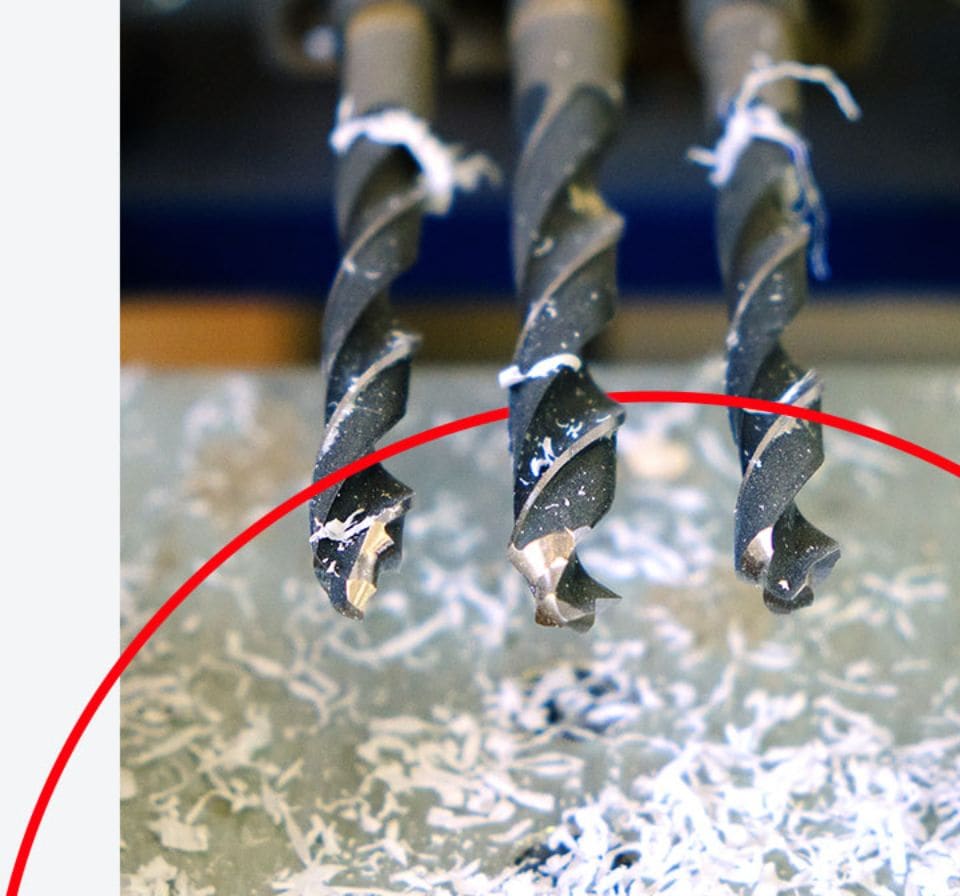
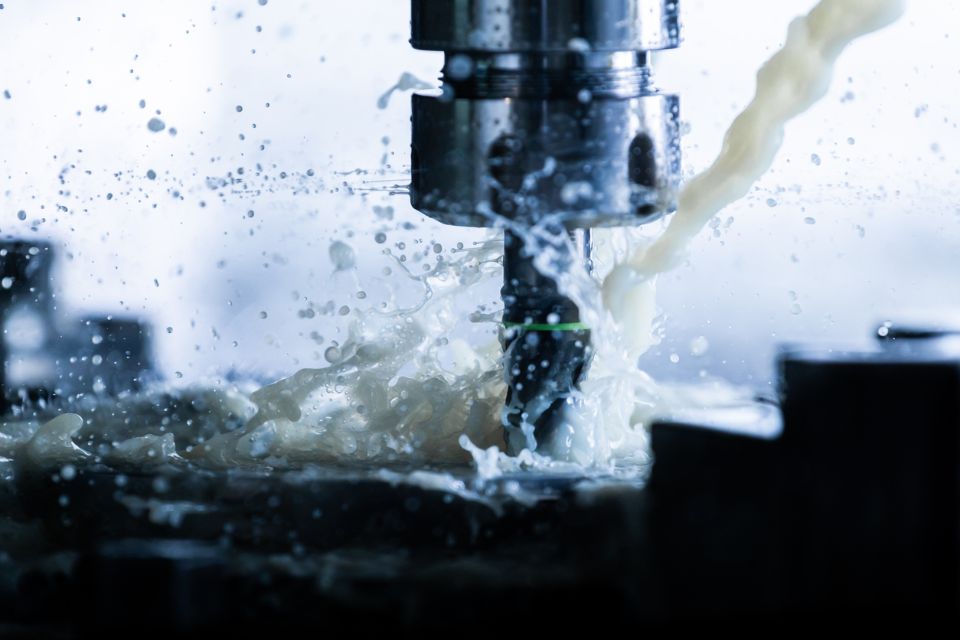
For their mechanical, chemical, and lightweight properties, plastics are increasingly replacing metals in a wide range of engineering applications. Many of the same machining methods used to fabricate metal parts are also used for plastics. However, best practices for machining plastics differ considerably from those for metals.
Plastics exhibit a number of properties that influence machining procedures, including:
- Thermal expansion of plastics is up to 20 times greater than that of metals
- Plastics lose heat more slowly than metals, increasing the risk of localized overheating
- Softening and melting temperatures of plastics are much lower than metals
- Plastics are much more elastic than metals
From material selection to proper tooling, from feed rates to stabilizing methods, part producers must weigh a range of factors in order to achieve good results when machining plastics. The following guidelines cover the most common plastic machining methods and provide useful tips and data for working with engineering polymers from Mitsubishi Chemical Group.
Read the overview below or download our Machinist’s Toolkit e-book, a complete fabrication guide including recommended speeds and tooling for a range of Mitsubishi Chemical Group materials.
Common plastic machining processes
-
This section covers the most common methods of machining plastic engineering components, providing guidelines and tips to achieve the best results with each.
Proper machining is crucial to achieving part dimensions and performance. Improper machining can create stress within the finished part, negatively impacting its mechanical properties and risking premature part failure.
Common causes of machined-in stress include:
• Using dull or improperly designed tooling
• Excessive heat generated from inappropriate speeds and feed rates
• Machining away large volumes of material, usually from one side of the stock shape -
What is threading? What is tapping?
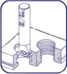
Tapping and threading are two machining methods used to produce screw threads. Threading is the process of using a die tool to carve external threads, where tapping is the process of using a tap tool to create threads on the inside of a drilled hole.
Threading and tapping with plastic vs. metal
A primary consideration when threading and tapping plastic is that plastics are more notch-sensitive than metals. Some polymer materials may tear during threading, especially in fine pitch procedures
Threading tips for plastic
Threading plastic should be done by single point using a carbide insert, taking four to five 0.001” passes at the end. Coolant usage is suggested.
Tapping tips for plastic
When tapping plastic, use the specified drill with a two-flute tap. Keep the tap clean of chip build-up. Use of a coolant during tapping is also suggested.
-

What is milling?
Milling is a machining method that applies a high-speed cylindrical cutting tool to a stationary plastic shape, moving the cutter on an axis to subtract from the shape in different directions. Computerized numerical control (CNC) milling refines accuracy and efficiency of plastic milling.
Milling plastic vs. metal
When milling plastic, it is crucial to properly stabilize the part on the worktable and minimize vibrations from the high-speed cutting tool – these may result in chatter marks and decreased accuracy due to the shape wandering.
Milling tips for plastic
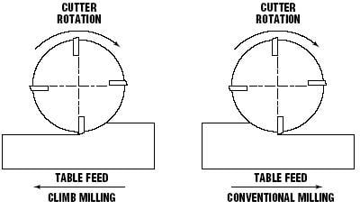
- Climb milling, also known as down milling, is recommended over conventional milling.
- Sufficient fixturing on the mill bed allows fast table travel and high spindle speeds.
- The shape should not be fixed too tightly, however, as it may deform or spring.
- When face milling, use positive geometry cutter bodies.
-

What is sawing?
Sawing is a machining method that involves cutting a material into multiple pieces using a bandsaw, table saw, or other specialized equipment.
Sawing plastic vs. metal
The primary difference between sawing plastic vs. metal is that the heat generated by the saw blade can negatively impact the plastic parts due to lower softening and melting temperatures. It is crucial to account for the speed of the blade, the thermal properties of the material, and the thickness of the shape when sawing plastic.
Tips for selecting a saw tool
- Band saws are versatile and perform well for straight, continuous curves, and irregular cuts.
- Table saws are convenient for straight cuts and can be used to cut multiple thicknesses and thicker cross sections – up to 4” with adequate horsepower.
Tips for selecting a saw blade
- Rip and combination blades with a 0° tooth rake and 3° to 10° tooth set are best for general sawing in order to reduce frictional heat.
- Hollow ground circular saw blades without set will yield smooth cuts up to 3/4” thickness.
- Tungsten carbide blades wear well and provide optimum surface finishes.
-
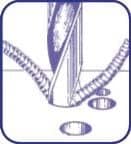
What is drilling? What is boring?
Drilling is a machining method that creates cylindrical holes and through-holes by means of a pointed helical tool. Boring is a secondary process for enlarging or finishing drilled holes.
Drilling and boring plastic vs. metal
The heat insulating characteristics of plastics require consideration during drilling operations, especially when the depth of the hole is greater than twice its diameter. Excessive heat build-up may result in chipping, rough surfaces, and inadequate tolerances.
Drilling tips for plasticFor small diameter holes (1/32” to 1”)
- High-speed steel twist drills are generally sufficient.
- Frequent pullout (peck drilling) is suggested to improve swarf removal.
- A slow spiral (low helix) drill will allow for better swarf removal.
For large diameter holes (1” and greater)
- A slow spiral (low helix) drill or general-purpose drill bit ground to a 118° point angle with 9° to 15° lip clearance is recommended. The lip rake should be ground (dubbed off) and the web thinned.
- Avoid hand feeding - drill grabbing can result in microcracks.
- It is generally best to drill a pilot hole (maximum 1/2” diameter) using 600 to 1000 rpm and a positive feed of 0.005” to 0.015” per revolution.
- Secondary drilling at 400 to 500 rpm at 0.008” to 0.020” per revolution is required to expand the hole to larger diameters.
For especially notch-sensitive materials (such as Ertalyte® PET-P and glass reinforced materials)
- A two-step process involving both drilling and boring minimizes heat build-up and reduces the risk of cracking.
- Firstdrill a 1” diameter hole using an insert drill at 500 to 800 rpm with a feed rate of 0.005” to 0.015” per revolution.
- Next bore the hole to final dimensions using a boring bar with carbide insert with 0.015” to 0.030” radii at 500 to 1000 rpm and a feed rate of 0.005” to 0.010” per revolution.
-

What is turning?
Turning is a machining process in which a plastic shape is rotated around a stationary lathe. Turning is especially useful for machining parts that are symmetrical along a common rotational axis.
Turning plastic vs. metal
As with other plastic machining processes, turning generates heat. In order to prevent damage to a plastic part, rotation speed, tool selection, and coolants should all be considered carefully along with the thermal properties of the material.
Turning tips for plastic
- Turning operations require inserts with positive geometries and ground peripheries.
- Ground peripheries and polished top surfaces generally reduce material build-up on the insert, improving the attainable surface finish.
- A fine-grained C-2 carbide is often recommended for plastic turning operations.
Additional treatments in machining
-
Depending on the requirements for the part and machining process, coolants and/or annealing may be recommended in order to improve the finished results. This section covers the use of coolants and annealing, as applicable in machining plastic parts.
-
What are coolants?
Coolants reduce the build-up of localized frictional heat, thus improving the machining results and extending the life of the tool. There are several types of coolants commonly used when machining engineering plastics, including air, dry ice, spray mists, and specially developed cooling agents.
When are cooling agents recommended?Coolants are not necessary for most machining practices and most engineering plastics. However, we recommend coolants in the following cases:
- When drilling or parting-off plastics – two processes that generate high frictional heat.
- When machining especially notch-sensitive materials, such as Ertalyte™ PET-P, Duratron™ PAI, Duratron™ PBI, and glass- or carbon-reinforced products.
- When it is necessary to achieve optimum surface finishes and close tolerances.
Tips for selecting a coolant
- Spray mists and pressurized air are very effective means of cooling the cutting interface.
- General purpose petroleum-based cutting fluids, although suitable for many metals and plastics, may contribute to stress cracking of amorphous plastics such as Altron™ PC, Sultron™ PSU, Sultron™ PPSU, and Duratron™ U1000 PEI.
- Two flood coolants suitable for most plastics are Trim E190 and Tim Sol LC SF.
-
What is annealing?
Annealing is a heat treatment process that improves the physical properties of a plastic, increasing its ductility and reducing its hardness to make the shape easier to machine. Annealing helps to relieve internal pressure from within the plastic, giving a machined part higher dimensional stability over time. The annealing process involves heating a plastic shape to half of its melt temperature for a determined period and letting it cool at a specific rate.
Annealing pre-machining
All plastic stock shapes from the Advanced Materials division of Mitsubishi Chemical Group are annealed using a proprietary stress relieving cycle that minimizes any internal stresses that may have resulted from the manufacturing process. This ensures that the material will remain dimensionally stable during and after machining.
Annealing post-machining
Few machined plastic parts require annealing after machining to meet dimensional or performance requirements; however, post-machining annealing does have several benefits, including:
- Improved chemical resistance – PC, PSU, and PEI materials can benefit from post-machining annealing to reduce stress crazing.
- Better flatness, tighter tolerances - Extremely close-tolerance parts requiring precision flatness and non-symmetrical contours sometimes require intermediate annealing between machining operations.
- High pressure velocity and low wear PAI - Extruded or injection- molded Duratron™ PAI parts requiring high pressure velocities or the lowest possible wear factor benefit from an additional cure after machining. This curing process optimizes the wear properties. Only PAI benefits from such a cycle.
Tips for annealing plastics- Improved flatness can be attained by rough machining, annealing, and finish machining with a very light cut.
- To reduce the potential for machined-in stress, review the fabrication guidelines for the specific material. Note that guidelines change as the material type changes.
- Ensure parts are fixtured to the necessary shape or flatness to prevent distortion. Do not unfix until the parts have completed the entire cycle and are cool to the touch.
- Finished machining to critical dimensions should be performed after annealing.
- Changes in heat- up and hold time may be possible if cross sections are thin.
Troubleshooting guidelines for engineering plastics
-
- Tapered hole
- Incorrectly sharpened drill
- Insufficient clearance
- Feed too heavy
- Burnt or melted surface
- Wrong drill type
- Incorrectly sharpened drill
- Feed too light
- Dull drill
- Web too thick
- Surface chipping
- Feed too heavy
- Clearance too great
- Too much rake (thin web as described)
- Chatter
- Clearance too great
- Feed too light
- Drill overhang too great
- Too much rake (thin web as described)
- Feed marks or spiral lines on inside diameter
- Feed too heavy
- Drill not centered
- Drill ground not centered
- Oversize holes
- Drill ground not centered
- Web too thick
- Insufficient clearance
- Feed rate too heavy
- Point angle too great
- Undersize holes
- Dull drill
- Too much clearance
- Point angle too small
- Holes not concentric
- Feed too heavy
- Spindle speed too slow
- Drill enters next piece too far
- Cut-off tool leaves nib, deflecting drill
- Web too thick
- Drill speed too heavy at start
- Drill not mounted at center
- Drill not sharpened correctly
- Burr at cut-off
- Dull cut-off tool
- Drill does not pass completely through piece
- Rapid dulling of drill
- Feed too light
- Spindle speed too fast
- Insufficient lubrication from coolant
- Tapered hole
-
- Melted surface
- Too dull or heel rubbing
- Insufficient side clearance
- Feed rate too slow
- Spindle speed too fast
- Rough finish
- Feed too heavy
- Incorrect clearance angles
- Sharp point on tool (slight nose radius required)
- Tool not mounted at center
- Burrs at edge of cut
- No chamfer provided at sharp corners
- Dull tool
- Insufficient side clearance
- Lead angle not provided on tool (tool should ease out of cut gradually, not suddenly)
- Cracking or chipping of corners
- Too much positive rake on tool
- Tool not eased into cut (suddenly hits work)
- Dull tool
- Tool mounted below center
- Sharp point on tool (slight nose radius required)
- Chatter
- Too much nose radius on tool
- Tool not mounted solidly
- Material not supported properly
- Width of cut too wide (use two cuts)
- Melted surface
-
- Melted surface
- Dull tool
- Insufficient side clearance
- Insufficient coolant supply
- Rough finish
- Feed too heavy
- Tool improperly sharpened
- Cutting edge not honed
- Spiral marks
- Tool rubs during its retreat
- Burr on point of tool
- Concave or convex surfaces
- Point angle too great
- Tool not perpendicular to spindle
- Tool deflecting
- Feed too heavy
- Tool mounted from above or below center
- Nibs or burrs at cut-off point
- Point angle not great enough
- Dull tool
- Feed too heavy
- Burrs on outside diameter
- No chamber before cut-off diameter
- Dull tool
- Melted surface
Download the complete Machinist's Toolkit
-
Recommended speeds, tooling, and more
Further information about our thermoplastic products Download our Machinist’s Toolkit e-book, a complete fabrication guide including recommended speeds and tooling for a range of Mitsubishi Chemical Group materials.
-
Common plastic machining processes
-
This section covers the most common methods of machining plastic engineering components, providing guidelines and tips to achieve the best results with each.
Proper machining is crucial to achieving part dimensions and performance. Improper machining can create stress within the finished part, negatively impacting its mechanical properties and risking premature part failure.
Common causes of machined-in stress include:
• Using dull or improperly designed tooling
• Excessive heat generated from inappropriate speeds and feed rates
• Machining away large volumes of material, usually from one side of the stock shape -

What is threading? What is tapping?
Tapping and threading are two machining methods used to produce screw threads. Threading is the process of using a die tool to carve external threads, where tapping is the process of using a tap tool to create threads on the inside of a drilled hole.
Threading and tapping with plastic vs. metal
A primary consideration when threading and tapping plastic is that plastics are more notch-sensitive than metals. Some polymer materials may tear during threading, especially in fine pitch procedures
Threading tips for plastic
Threading plastic should be done by single point using a carbide insert, taking four to five 0.001” passes at the end. Coolant usage is suggested.
Tapping tips for plastic
When tapping plastic, use the specified drill with a two-flute tap. Keep the tap clean of chip build-up. Use of a coolant during tapping is also suggested.
-

What is milling?
Milling is a machining method that applies a high-speed cylindrical cutting tool to a stationary plastic shape, moving the cutter on an axis to subtract from the shape in different directions. Computerized numerical control (CNC) milling refines accuracy and efficiency of plastic milling.
Milling plastic vs. metal
When milling plastic, it is crucial to properly stabilize the part on the worktable and minimize vibrations from the high-speed cutting tool – these may result in chatter marks and decreased accuracy due to the shape wandering.

Milling tips for plastic
- Climb milling, also known as down milling, is recommended over conventional milling.
- Sufficient fixturing on the mill bed allows fast table travel and high spindle speeds.
- The shape should not be fixed too tightly, however, as it may deform or spring.
- When face milling, use positive geometry cutter bodies.
-

What is sawing?
Sawing is a machining method that involves cutting a material into multiple pieces using a bandsaw, table saw, or other specialized equipment.
Sawing plastic vs. metal
The primary difference between sawing plastic vs. metal is that the heat generated by the saw blade can negatively impact the plastic parts due to lower softening and melting temperatures. It is crucial to account for the speed of the blade, the thermal properties of the material, and the thickness of the shape when sawing plastic.
Tips for selecting a saw tool
- Band saws are versatile and perform well for straight, continuous curves, and irregular cuts.
- Table saws are convenient for straight cuts and can be used to cut multiple thicknesses and thicker cross sections – up to 4” with adequate horsepower.
Tips for selecting a saw blade
- Rip and combination blades with a 0° tooth rake and 3° to 10° tooth set are best for general sawing in order to reduce frictional heat.
- Hollow ground circular saw blades without set will yield smooth cuts up to 3/4” thickness.
- Tungsten carbide blades wear well and provide optimum surface finishes.
-

What is drilling? What is boring?
Drilling is a machining method that creates cylindrical holes and through-holes by means of a pointed helical tool. Boring is a secondary process for enlarging or finishing drilled holes.
Drilling and boring plastic vs. metal
The heat insulating characteristics of plastics require consideration during drilling operations, especially when the depth of the hole is greater than twice its diameter. Excessive heat build-up may result in chipping, rough surfaces, and inadequate tolerances.
Drilling tips for plasticFor small diameter holes (1/32” to 1”)
- High-speed steel twist drills are generally sufficient.
- Frequent pullout (peck drilling) is suggested to improve swarf removal.
- A slow spiral (low helix) drill will allow for better swarf removal.
For large diameter holes (1” and greater)
- A slow spiral (low helix) drill or general-purpose drill bit ground to a 118° point angle with 9° to 15° lip clearance is recommended. The lip rake should be ground (dubbed off) and the web thinned.
- Avoid hand feeding - drill grabbing can result in microcracks.
- It is generally best to drill a pilot hole (maximum 1/2” diameter) using 600 to 1000 rpm and a positive feed of 0.005” to 0.015” per revolution.
- Secondary drilling at 400 to 500 rpm at 0.008” to 0.020” per revolution is required to expand the hole to larger diameters.
For especially notch-sensitive materials (such as Ertalyte® PET-P and glass reinforced materials)
- A two-step process involving both drilling and boring minimizes heat build-up and reduces the risk of cracking.
- Firstdrill a 1” diameter hole using an insert drill at 500 to 800 rpm with a feed rate of 0.005” to 0.015” per revolution.
- Next bore the hole to final dimensions using a boring bar with carbide insert with 0.015” to 0.030” radii at 500 to 1000 rpm and a feed rate of 0.005” to 0.010” per revolution.
-

What is turning?
Turning is a machining process in which a plastic shape is rotated around a stationary lathe. Turning is especially useful for machining parts that are symmetrical along a common rotational axis.
Turning plastic vs. metal
As with other plastic machining processes, turning generates heat. In order to prevent damage to a plastic part, rotation speed, tool selection, and coolants should all be considered carefully along with the thermal properties of the material.
Turning tips for plastic
- Turning operations require inserts with positive geometries and ground peripheries.
- Ground peripheries and polished top surfaces generally reduce material build-up on the insert, improving the attainable surface finish.
- A fine-grained C-2 carbide is often recommended for plastic turning operations.
-
-
Additional treatments in machining
-
Depending on the requirements for the part and machining process, coolants and/or annealing may be recommended in order to improve the finished results. This section covers the use of coolants and annealing, as applicable in machining plastic parts.
-
What are coolants?
Coolants reduce the build-up of localized frictional heat, thus improving the machining results and extending the life of the tool. There are several types of coolants commonly used when machining engineering plastics, including air, dry ice, spray mists, and specially developed cooling agents.
When are cooling agents recommended?Coolants are not necessary for most machining practices and most engineering plastics. However, we recommend coolants in the following cases:
- When drilling or parting-off plastics – two processes that generate high frictional heat.
- When machining especially notch-sensitive materials, such as Ertalyte™ PET-P, Duratron™ PAI, Duratron™ PBI, and glass- or carbon-reinforced products.
- When it is necessary to achieve optimum surface finishes and close tolerances.
Tips for selecting a coolant
- Spray mists and pressurized air are very effective means of cooling the cutting interface.
- General purpose petroleum-based cutting fluids, although suitable for many metals and plastics, may contribute to stress cracking of amorphous plastics such as Altron™ PC, Sultron™ PSU, Sultron™ PPSU, and Duratron™ U1000 PEI.
- Two flood coolants suitable for most plastics are Trim E190 and Tim Sol LC SF.
-
What is annealing?
Annealing is a heat treatment process that improves the physical properties of a plastic, increasing its ductility and reducing its hardness to make the shape easier to machine. Annealing helps to relieve internal pressure from within the plastic, giving a machined part higher dimensional stability over time. The annealing process involves heating a plastic shape to half of its melt temperature for a determined period and letting it cool at a specific rate.
Annealing pre-machining
All plastic stock shapes from the Advanced Materials division of Mitsubishi Chemical Group are annealed using a proprietary stress relieving cycle that minimizes any internal stresses that may have resulted from the manufacturing process. This ensures that the material will remain dimensionally stable during and after machining.
Annealing post-machining
Few machined plastic parts require annealing after machining to meet dimensional or performance requirements; however, post-machining annealing does have several benefits, including:
- Improved chemical resistance – PC, PSU, and PEI materials can benefit from post-machining annealing to reduce stress crazing.
- Better flatness, tighter tolerances - Extremely close-tolerance parts requiring precision flatness and non-symmetrical contours sometimes require intermediate annealing between machining operations.
- High pressure velocity and low wear PAI - Extruded or injection- molded Duratron™ PAI parts requiring high pressure velocities or the lowest possible wear factor benefit from an additional cure after machining. This curing process optimizes the wear properties. Only PAI benefits from such a cycle.
Tips for annealing plastics- Improved flatness can be attained by rough machining, annealing, and finish machining with a very light cut.
- To reduce the potential for machined-in stress, review the fabrication guidelines for the specific material. Note that guidelines change as the material type changes.
- Ensure parts are fixtured to the necessary shape or flatness to prevent distortion. Do not unfix until the parts have completed the entire cycle and are cool to the touch.
- Finished machining to critical dimensions should be performed after annealing.
- Changes in heat- up and hold time may be possible if cross sections are thin.
-
-
Troubleshooting guidelines for engineering plastics
-
- Tapered hole
- Incorrectly sharpened drill
- Insufficient clearance
- Feed too heavy
- Burnt or melted surface
- Wrong drill type
- Incorrectly sharpened drill
- Feed too light
- Dull drill
- Web too thick
- Surface chipping
- Feed too heavy
- Clearance too great
- Too much rake (thin web as described)
- Chatter
- Clearance too great
- Feed too light
- Drill overhang too great
- Too much rake (thin web as described)
- Feed marks or spiral lines on inside diameter
- Feed too heavy
- Drill not centered
- Drill ground not centered
- Oversize holes
- Drill ground not centered
- Web too thick
- Insufficient clearance
- Feed rate too heavy
- Point angle too great
- Undersize holes
- Dull drill
- Too much clearance
- Point angle too small
- Holes not concentric
- Feed too heavy
- Spindle speed too slow
- Drill enters next piece too far
- Cut-off tool leaves nib, deflecting drill
- Web too thick
- Drill speed too heavy at start
- Drill not mounted at center
- Drill not sharpened correctly
- Burr at cut-off
- Dull cut-off tool
- Drill does not pass completely through piece
- Rapid dulling of drill
- Feed too light
- Spindle speed too fast
- Insufficient lubrication from coolant
- Tapered hole
-
- Melted surface
- Too dull or heel rubbing
- Insufficient side clearance
- Feed rate too slow
- Spindle speed too fast
- Rough finish
- Feed too heavy
- Incorrect clearance angles
- Sharp point on tool (slight nose radius required)
- Tool not mounted at center
- Burrs at edge of cut
- No chamfer provided at sharp corners
- Dull tool
- Insufficient side clearance
- Lead angle not provided on tool (tool should ease out of cut gradually, not suddenly)
- Cracking or chipping of corners
- Too much positive rake on tool
- Tool not eased into cut (suddenly hits work)
- Dull tool
- Tool mounted below center
- Sharp point on tool (slight nose radius required)
- Chatter
- Too much nose radius on tool
- Tool not mounted solidly
- Material not supported properly
- Width of cut too wide (use two cuts)
- Melted surface
-
- Melted surface
- Dull tool
- Insufficient side clearance
- Insufficient coolant supply
- Rough finish
- Feed too heavy
- Tool improperly sharpened
- Cutting edge not honed
- Spiral marks
- Tool rubs during its retreat
- Burr on point of tool
- Concave or convex surfaces
- Point angle too great
- Tool not perpendicular to spindle
- Tool deflecting
- Feed too heavy
- Tool mounted from above or below center
- Nibs or burrs at cut-off point
- Point angle not great enough
- Dull tool
- Feed too heavy
- Burrs on outside diameter
- No chamber before cut-off diameter
- Dull tool
- Melted surface
-
-
Download the complete Machinist's Toolkit
-
Recommended speeds, tooling, and more
Further information about our thermoplastic products Download our Machinist’s Toolkit e-book, a complete fabrication guide including recommended speeds and tooling for a range of Mitsubishi Chemical Group materials.
-
Get in touch with our specialist teams by filling in the contact form. We’re ready to meet your next challenge.

